Johnson Service Bulletin #637 (1958) - Carburetor Fuel Saver and Cam Follower Adjustment

Issued March 21, 1958, for the Johnson V-50 series, this three-page bulletin explains the fuel saver throttle range, the relationship between spark advance and throttle opening, and how to adjust the carburetor cam follower assembly. It includes four original factory illustrations and references SB-607 and SB-627.

Johnson Service Bulletin letterhead
March 21, 1958SERVICE BULLETIN #637
CARBURETOR-FUEL SAVER AND ADJUSTING CAM FOLLOWER
LEVER TO THROTTLE PLATE BRACKET - MODEL V-50 SERIES
REFERENCE: Service Bulletin #607 - Replacing Magneto Driving Belt and Timing Magneto
REFERENCE: Service Bulletin #627 - To Synchronize Spark and Gas
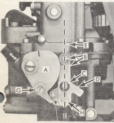
Figure 1: V-50 throttle cam and cam follower at idle speed
Figure 1
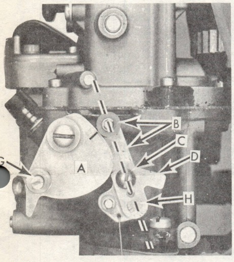
Figure 2: V-50 throttle cam and cam follower at intermediate speed
Figure 2

The above subject service bulletins illustrate and describe replacing of the magneto driving belt, timing of the magneto and synchronizing of spark and gas. The illustrations and following instructions included here, relate to the fuel saver and proper adjustment of the cam follower lever with respect to position of the throttle plates in both barrels of the dual carburetor -

V-50 Series

Like the RD series, provisions are made in the V-50 for cruising at fuel saving speeds once the boat has gained its plane. Full power, however is applied to reach planing position after which on most planing runabouts, the throttle may be pulled back slightly to partially close the throttle plate without affecting position of spark advance. This permits operation at full spark advance with partial closing of the carburetor throttle plate to reduce fuel consumption with an almost imperceptible falling off of boat speed in many instances. Weight and type of boat, load and nature of service obviously are factors contributing to performance in the "fuel saver range" of operation.

Fig. 1 - Illustrates position of the throttle cam (a) and cam follower assembly (b) at slow or idle speed.

Fig. 2 - Illustrates position of the throttle cam (a) and cam follower assembly (b) at intermediate speed - low end of the fuel saver range at full spark advance.

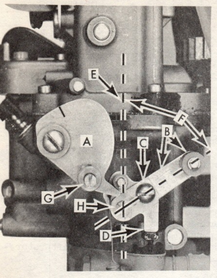
Fig. 3 - Illustrates position of the throttle cam (a) and cam follower assembly (b) at full open (top speed and power) and indicates range or degree of throttle plate movement (f) beyond full spark advance (fuel saver range).

OVER
Superior Service Spells Satisfaction
SERVICE BULLETIN #637 - page 2
Figure 3: full throttle cam position and linkage markings A through H
Figure 3
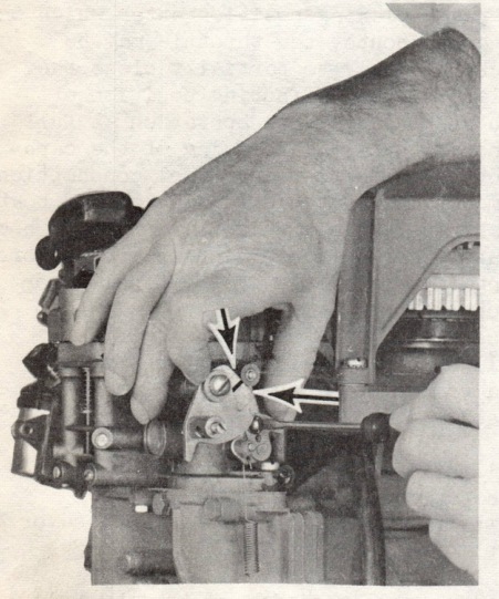
Figure 4: hand positioning bracket D for cam follower adjustment
Figure 4

To fully observe and comprehend, it may perhaps be advisable to remove the cover from one of the V-50's on your display floor to actually duplicate the above throttle positions in each instance. (The rod linking the carburetor and throttle cam with the magneto linkage has been omitted for purposes of unobstructed illustration.)

NOTE: Cam follower (roller) and lever assembly "B", bracket (D) and throttle plate adjusting screw "C".

The cam follower and lever assembly "B" floats on throttle plate shaft "H". Bracket "D", provided with an elongated hole for adjusting purposes, is "swedged" to throttle plate shaft "H" and as such becomes an integral part of the assembly.

The throttle plate and cam follower assembly are precisely adjusted at the factory and should require no other attention unless adjusting screw "C" has been unwittingly loosened and the throttle plate subsequently "thrown" out of adjustment with the cam follower to affect over all motor performance.

To check and/or readjust position of the throttle plate with respect to position of the cam follower assembly, proceed as follows:

  1. Loosen screw "G" and remove carburetor synchronizing link to gain easy access to adjusting screw "C".
  2. Loosen screw "C".
  3. Turn throttle cam "A" to position where synchronizing score mark falls in line with center of the cam following roller - at point of contact with cam contour.
  4. Place fore finger against cam plate with thumb bearing against bracket "D" as shown Fig. 4. Move bracket "D" with thumb to limit of its travel in direction indicated by arrow.
  5. Making sure the cam roller contacts contour of cam at score mark provided for the purpose, tighten "C" to secure in this position.
  6. Replace synchronizing link - adjust as instructed in Service Bulletin #627 and as illustrated Fig. 1.
SERVICE BULLETIN #637 - page 3

7. Check adjustment - if correct, the throttle plate in the carburetor barrel should just "break" at instant of speed control (lever) advance.

Purpose of adjusting throttle plate bracket "D" and securing it to the cam follower assembly "B" is to properly locate position of the throttle plate (in the carburetor barrels) for idle setting - the throttle plate must be definitely closed when the cam follower (roller) makes contact with the cam contour at point of synchronizing or score line embossed on the face of the cam plate "A" Figure 1.

Very truly yours,
JOHNSON MOTORS
Arvid Olson
Arvid Olson
Service Promotion Manager
AO:vl
Back to service bulletin index