March 27, 1961
Bulletin No. SB-836
Alternator Charging Circuit
(Supplement to SB-832)
SUBJECT: Jammed voltage regulators cause sharp amperage drops;
75 h.p. alternator models V4A & V4AL-13 & 13C.
Many of you have by now probably observed that the transistorized voltage regulator used
with the alternator equipped engine is mounted on rubber within the junction box. The
purpose of rubber mounting is to suppress vibration so the regulator can function as
intended to control opening and closing of its contact points. This function of the
regulator can however be overcome by carelessly stuffing the nylon connector into the
junction box in such a manner that it becomes wedged between the regulator and the
junction box cover. Should such jamming occur, vibration will be transmitted to, and
override, the regulator which in turn will cause the alternator to generate erratically.
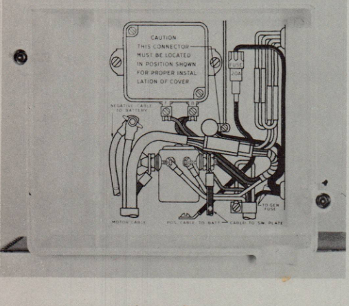
To avoid the foregoing possibility, be certain to locate the nylon connector and all
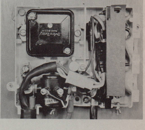
other junction box components as illustrated inside the cover, figure 1. Figure 2
illustrates the actual location of the various components within the junction box.
Note the location of the 20-amp accessory fuse holder and the rectifier leads. These
components must be located as illustrated and all other wiring must be clear of the
regulator. With the connector located as illustrated in figure 2, the motor cable
must allow sufficient clearance above the FL and BAT terminals to insure unrestrained
operation of the regulator. Because the motor cable is quite stiff, it may be necessary
to bend it in order to locate it in the required position.
Figure 1
Figure 2
SYMPTOMS AND DIAGNOSES OF JAMMED REGULATORS:
When all components of the charging circuit function normally, the alternator generates
approximately 5 amps at 500-600 rpm to a maximum of 20 amps at 2500 rpm and higher.
If the regulator becomes jammed the rate of charge may appear to be normal up to about
Over