Johnson Service Bulletin SB-946 - Insulator Sleeve for Electramatic Engines
March 21, 1963. Four-page factory bulletin covering Silver-Flex shift lead insulation, installation procedures for 40 and 75 HP engines, and affected engine serial numbers.
March 21, 1963
Bulletin No. SB-946
Lower Unit
SUBJECT: INSULATOR SLEEVE - for gearcase shift lead -
all "ELECTRAMATIC" Engines.
A 'Silver-Flex' insulating sleeve is now available for use on all 40 and 75 h.p.
ELECTRAMATIC engines. Installed over the gearcase shift lead it protects the lead
from abnormally high exhaust tube temperatures that result from engine overload.
Prolonged engine overload (too high pitched propeller, or, towing another craft
at advanced throttle) produces a substantial temperature increase in the exhaust tube
which in some instances results in burning of the shift lead. Naturally, this shorts
out the electric shift circuit.
Figure 1
The 'Silver Flex' sleeve is available in two lengths for standard and long shaft
engines (see figure 1). List prices of these sleeves are:
309807 - - $ .70 each
309808 - - .80 each
Order only from your Parts Distributor. Your standard parts discount applies.
You will note that the ends of these sleeves are coated. This prevents unraveling
during installation. In the event you are out of the short sleeve (309807) it is
permissible to cut 5" off the long sleeve for use in a standard length motor.
Re-coat the cut end as follows:
Coat approximately 1/4" at the end of the sleeve with sealer 1000.
Slip a punch or similar round object into the newly coated sleeve
end until the sealer dries. This prevents the sleeve from sticking
together at the end.
INSTALLATION OF INSULATING SLEEVE ON 40 H.P. ENGINES.
1. Remove rear exhaust cover (378969). Remove gearcase extension
cover (port and star. sections) if engine is RKL model.
2. Disconnect gearcase shift lead at powerhead - blue and green wires.
3. Remove exhaust cover plate (305740) and exhaust housing plate (308346).
SB-946
page 2
4. Remove gearcase from exhaust housing - 6 screws.
a. Remove pump housing and impeller from gearcase.
b. Remove impeller key and driveshaft from gearcase.
5. Slip insulating sleeve over shift lead - 309807 sleeve for model
RK, 309808 sleeve for model RKL, so that bottom end of sleeve
butts against lead retainer at top of upper gearcase.
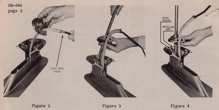
6. Tape upper end of sleeve to shift lead, figure 2, just above
ribbed area.
7. Thread lead through water pump housing, figure 2, and position
pump housing approximately 5" from top of gearcase on insulating
sleeve.
8. Insert driveshaft through top of pump housing and impeller so that
4" or 5" of shaft protrudes from bottom of impeller housing.
9. Position pump plate on top of gearcase with convex side up.
10. Proceed to insert driveshaft into top of gearcase (figure 3).
Hold bottom of pump housing while inserting driveshaft into
gearcase, to prevent pump impeller from slipping out of housing.
Allow enough room between pump housing and top of gearcase during
this operation for installation of impeller key.
11. Install impeller key in driveshaft (figure 4) and carefully
bring pump housing and impeller toward gearcase - to engage
key with pump impeller.
12. Secure impeller housing to gearcase (4 screws) and draw shift
lead taunt through opening in pump housing.
13. Remove tape from top of insulating sleeve.
14. Draw shift lead through exhaust tube opening and secure gearcase
to exhaust housing (6 screws).
SB-946
Page 3
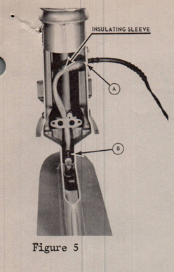
15. Install cover plate (308346) over shift lead -
making sure small projection on inside of
cover plate slips inside top end of insulating
sleeve (figure 5).
16. Proceed to assemble outer cover plate (305740)
and attach shift lead to its respective
connectors at powerhead (blue to blue and
green to green). Assemble rear exhaust cover
and extension housing covers (port and star
sections) if engine is RKL model.
INSTALLATION OF INSULATING SLEEVE ON 75 H.P. ENGINES.
1. Remove rear exhaust cover (305099).
2. Disconnect gearcase shift lead at power-
head - blue and green wires.
3. Remove exhaust cover plate 305405
and exhaust housing plate 308308.
4. See Service bulletin number SB-947 and
proceed as outlined therein, to insure
maximum protection of shift lead wires.
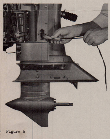
5. Slip insulating sleeve over shift
lead - 309807 sleeve for model V4A,
309808 sleeve for model V4AL, so that
bottom end of sleeve butts against lead
retainer at top of upper gearcase.
See Figure 6.
6. Install 308308 cover plate over shift
lead, making sure small projection on
inside of cover plate slips inside top
end of insulating sleeve.
7. Proceed to re-assemble outer cover plate
305405 and attach shift lead to its
respective connectors at the powerhead
(blue to blue and green to green).
Assemble rear exhaust cover.
over
SB-946
Page 4
We suggest installing this sleeve on all of the following engines as they are
brought in for any service to avoid the possibility of shorted shift circuits.
All 1962 - Model - RK-24 engines
RKL-24 engines
V4A-14 engines
V4AL-14 engines
All 1963 - Model - RK-25D engines prior to serial #2341603
RKL-25D engines prior to serial #2343970
V4A-15 Engines prior to serial #2346488
V4AL-15 Engines prior to serial #2350144
Engines made after the serial numbers listed for 1963 engines have had the sleeve
installed here at the factory.
Sincerely,
JOHNSON MOTORS
Robert Compton
Service Department
RC:eb
NOTE: Post on your RK-40 h.p. and V-75 h.p. indexes.
Related service bulletin
The 75 HP installation procedure on page 3 refers to SB-947 for protecting the shift lead wires.