March 11, 1963
Bulletin No. SB-947
Lower Unit
SUBJECT: #378535 Electric Shift Lead Burning - 1962 and 1963 'ELECTRAMATIC' Engines-75 H.P.
Field reports indicate that the insulation on part #378535 shift cable is occasionally
burned just above the water pump on the subject engines, resulting in a shorted
(inoperative) electric shift circuit. While this is not to be considered a common
occurrence, it nevertheless does occasionally present itself under certain applications
of motor usage. It has been determined that severe overload conditions, i.e., too
high pitched propeller or towing another craft at advanced throttle, etc., are
principal causes of this burning, due to the abnormally high temperatures which pre-
vails inside the exhaust housing at the time.
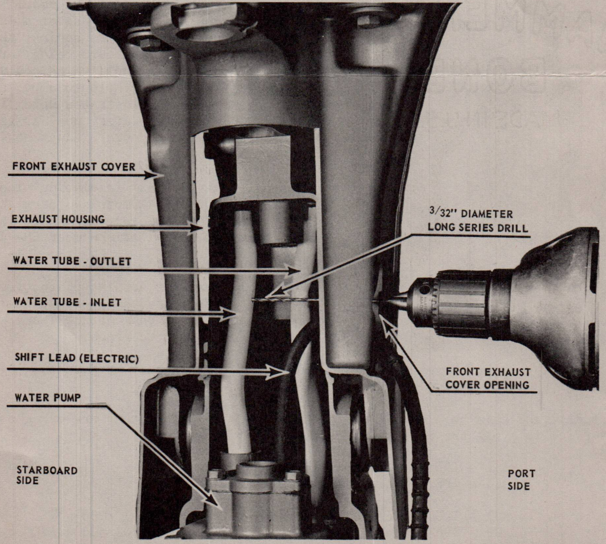
This problem is easily prevented by drilling a 3/32" diameter hole into the INLET
water tube as shown in the cutaway illustration - figure 1. So doing directs a
spray of cool water over the cable to reduce temperature in the area and prevent
burning.
Figure 1. Cutaway view of lower unit from front of engine.
over
Page 3
SB-947
For maximum protection install the 'Silver-Flex' insulating sleeve on the shift lead
of any engine that is not already equipped with this item along with the drilling of
this hole in the water tube.
Dealers should include as standard servicing procedure - periodic visual inspections
of the water spray hole (especially in salt water areas) to prevent clogging due to
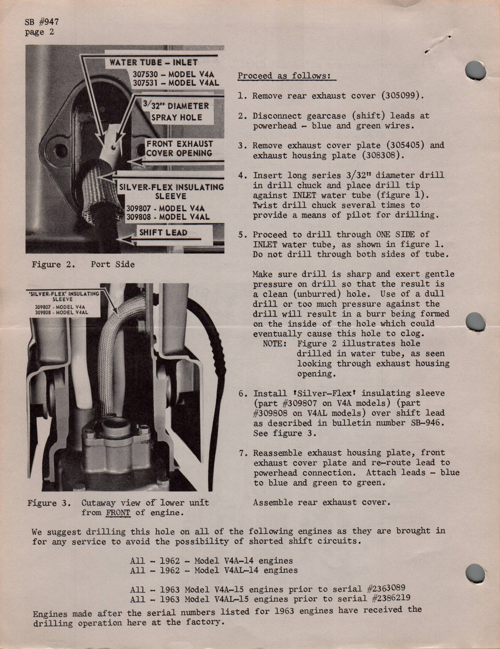
salt corrosion or other conditions. A piece of fairly stiff wire can be used to
probe the hole clear if clogged. To do this merely remove #305405 and #308308 covers.
See figure 3.
Careful examination of new (replacement) inlet water tubes, parts 307530 and 307531
(long), should always be made prior to installation on the motor to make sure either
length tube has TWO 3/32" diameter holes. Prior to this bulletin, both lengths of
inlet water tubes had only one drilled hole - located 2 inches from the bottom
(unflared end) on part 307530, and 7 inches from the bottom (unflared end) on part
307531. If the inlet tube being installed does not have the second hole, drill this
hole after installation according to step 4 and figure 1, so that the water stream
is directed straight at the shift cable. In the event the inlet water tube being
installed does have the second hole, it should be twisted to deflect water spray
straight at the shift lead after its installation. This must be done prior to
securing the gearcase to the exhaust tube. Here again, the position of the water
hole can be observed by glancing through the opening in the exhaust tube as shown
in figure 2.
Sincerely,
JOHNSON MOTORS
Robert Compton
Service Department
RC:eb
NOTE: Post on your V-75 index.