LOWER UNIT 1017
JULY 1973
NEW NEUTRAL DETENT FEATURE ADDED ON 1973, 50 THRU 135 HP MODELS
As the result of field and Florida tests, we decided to add the shift
detent feature to our 1973 thru hub exhaust gearcases. This is
primarily to improve shift dog life and aid the technician in locating
the neutral position during cable installation. Adjusting for correct
forward and reverse overtravel will be easier. The detented shift
started with the following model and serial numbers:
detent feature to our 1973 thru hub exhaust gearcases. This is
primarily to improve shift dog life and aid the technician in locating
the neutral position during cable installation. Adjusting for correct
forward and reverse overtravel will be easier. The detented shift
started with the following model and serial numbers:
50372 - 01351
50373 - 06784
65372 - 01270
65373 - 09375
50373 - 06784
65372 - 01270
65373 - 09375
85393 - 05550
115393 - 06350
135383 - 05350
115393 - 06350
135383 - 05350
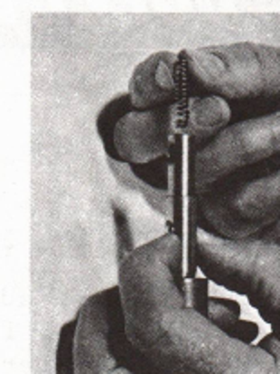
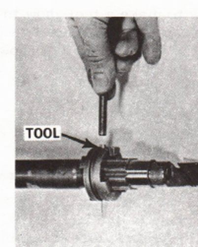
The following illustrations show how to make a tool, how to assemble
and disassemble the unit and how to tell the difference between the
parts used in the 50 and 65 HP and the V-4's. The tool shown in
Figure 1 can be made with a 9/32" piece of drill rod.
and disassemble the unit and how to tell the difference between the
parts used in the 50 and 65 HP and the V-4's. The tool shown in
Figure 1 can be made with a 9/32" piece of drill rod.
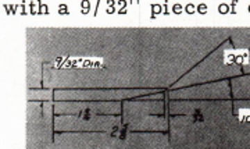
FIGURE 1
The 50 and 65 HP parts are shown at the bottom of Figure 2. The
propeller shaft (A), clutch dog pin spring (B), clutch dog (C) and
shift rod (G) are different from the V-4's and these differences
can be seen in Figure 2.
propeller shaft (A), clutch dog pin spring (B), clutch dog (C) and
shift rod (G) are different from the V-4's and these differences
can be seen in Figure 2.
The detent activating springs are distinguishable by size and color.
The 50 and 65 HP spring, P/N 318575, is shorter and colored black.
The P/N 318576 used in the V-4's is red and longer. The detent balls (F)
P/N 316506 are the same and three are required.
The 50 and 65 HP spring, P/N 318575, is shorter and colored black.
The P/N 318576 used in the V-4's is red and longer. The detent balls (F)
P/N 316506 are the same and three are required.
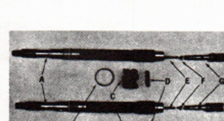
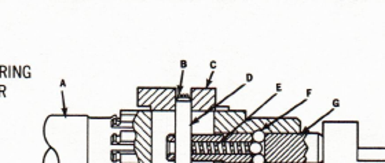
A. PROPELLER SHAFT
B. CLUTCH DOG PIN SPRING
C. CLUTCH DOG
D. CLUTCH DOG SHIFTER
E. DETENT SPRING
F. DETENT BALL
G. SHIFT ROD
B. CLUTCH DOG PIN SPRING
C. CLUTCH DOG
D. CLUTCH DOG SHIFTER
E. DETENT SPRING
F. DETENT BALL
G. SHIFT ROD
FIGURE 2A
FIGURE 2B