
ACCESSORIES #1018
July, 1973
INSTALLING POWER TILT KIT #172509
ON 1973, 65 LONG AND V-4 MODELS
ON 1973, 65 LONG AND V-4 MODELS
When installing a 172509 Power Tilt Kit on the above model outboards, the swivel bracket must be modified to allow the tilt cylinder to clear.
If the boss is not modified, the band on the tilt cylinder will interfere with the swivel bracket when the thrust rod is in the position closest to the transom.
Please refer to photographs below of modified and original brackets.
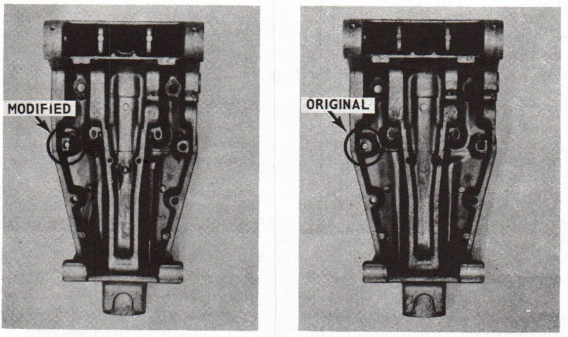
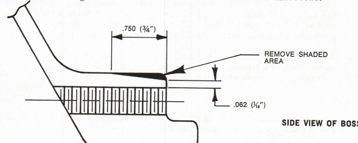
Use a file (rotary works best) to remove a wedge shaped portion from the boss. Begin 1/16" from the outside thread area on the boss and angle down 3/4". This will result in a 60° angle flat surface after removal of the material.
Proceed with the installation of the kit.
After the kit has been installed cycle the unit up and down several times to make certain no interference occurs in this area.
After the kit has been installed cycle the unit up and down several times to make certain no interference occurs in this area.
EVINRUDE MOTORS
Service Department
Service Department