SB-1302 - New Steering System Recommendations
Issued August 1972, this Johnson Service Bulletin introduces the 1973 OMC Rotomatic steering system and reproduces the factory steering installation instructions, including parts lists, cable measurements, pulley-cable arrangements and steering safety requirements.

The 1973 models listed above have been redesigned to accept the new OMC Rotomatic steering system. The installation and recommended combination of parts for this new system is different than that used in 1972. For your convenience, we are reprinting on the following pages a copy of the installation instructions packaged in every owners kit. Note especially the recommendations for dual engine installations. Under no circumstances should a dual installation be made using a single cable and tie bar.
FOR 50, 65 LONG, 85, 115, AND 135 HP OUTBOARDS
As delivered, this engine is equipped for OMC Thru-Tilt Steering. The following accessory kits are required to complete the installation.
SINGLE ENGINE
| QTY. | PART NO. | DESCRIPTION | MODEL |
|---|---|---|---|
| 1 | 172404 | Steering Wheel (see accessory catalog for additional wheels) | ALL |
| 1 | 172609 | Rotary Helm Assy | ALL |
| 1 | 385707 | Steering Rod Kit | 50 HP |
| 1 | 385708 | Steering Rod Kit | 65 HP Long, 85-135 HP |
| 1 | See Below | Steering Cable | ALL |
▣ NOTE
These kits include instructions which should be followed carefully for correct installation.
DUAL ENGINE
| QTY. | PART NO. | DESCRIPTION | MODEL |
|---|---|---|---|
| 1 | 172404 | Steering Wheel (see accessory catalog for additional wheels) | ALL |
| 1 | 172608 | Rotary Helm Assy | ALL |
| 2 | 385707 | Steering Rod Kit | 50 HP |
| 2 | 385708 | Steering Rod Kit | 65 HP Long, 85-135 HP |
| 1 | 385709 | Steering Tie Bar Kit (26-inch centers) | ALL |
| 2 | See Below | Steering Cable | ALL |
HOW TO MEASURE CABLE FOR OMC THRU-TILT STEERING
To determine length of cable required, place engine in straight-ahead position, and use method outlined below.
1. Select a path from helm to engine that is free from obstructions.
2. Calculate cable length using this formula:
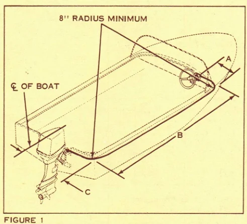
Single Engine: A+B+C+1 ft. = approximate cable length. See Figure 1.
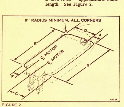
Dual Engine: A+B+C+1 ft. = approximate cable length. D+E+F+1 ft. = approximate cable length. See Figure 2.
3. For dual engine boats with walk-thru dash panels, determine cable lengths as follows.
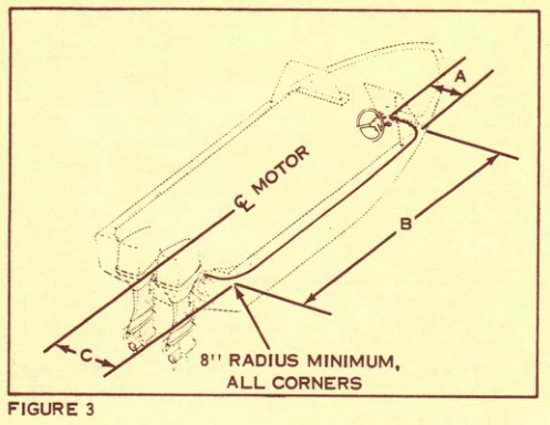
Formula A+B+C+1 ft. will provide approximate cable length necessary to connect helm to nearest engine. See Figure 3.
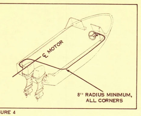
For second cable, select a path similar to one shown in Figure 4. Measure along route from helm to centerline of farthest engine, and add three feet to this distance. This will give the approximate length of cable required.
4. When mounting, be sure to allow for a 8-inch minimum radius at each bend of cable.
Cables are available in one foot increments from ten feet through thirty feet.
| PART NO. | LENGTH | PART NO. | LENGTH |
|---|---|---|---|
| 172610 | 10 ft. | 172621 | 21 ft. |
| 172611 | 11 ft. | 172622 | 22 ft. |
| 172612 | 12 ft. | 172623 | 23 ft. |
| 172613 | 13 ft. | 172624 | 24 ft. |
| 172614 | 14 ft. | 172625 | 25 ft. |
| 172615 | 15 ft. | 172626 | 26 ft. |
| 172616 | 16 ft. | 172627 | 27 ft. |
| 172617 | 17 ft. | 172628 | 28 ft. |
| 172618 | 18 ft. | 172629 | 29 ft. |
| 172619 | 19 ft. | 172630 | 30 ft. |
| 172620 | 20 ft. | 172640 | 31-40 ft. (specify length) |
For cables thirty-one feet through forty feet, order part no. 172640 and specify length.
PULLEY-CABLE STEERING SYSTEM
If pulley-cable steering is desired, the following accessory kits must be used.
| QTY. | PART NO. | DESCRIPTION | MODEL |
|---|---|---|---|
| 1 | 386027 | Steering Kit - single engine | 50, 65, 85 thru 135 HP |
| 1 | 385970 | Steering Kit - single engine | 50 HP Rope |
| 1 | 172423 | Helm Assembly | All |
| 1 | 172404 | Steering Wheel (see accessory catalog) | All |
Two kits are required for dual motor installations.
These steering kits contain anchor brackets which must be connected to the steering arm.
▣ NOTE
Do not attempt to connect pulley links directly to the engine steering arm without using anchor brackets.
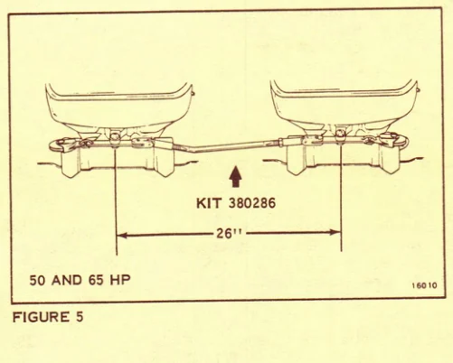
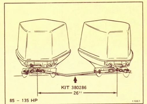
For twin motor installations, use dual steering tie bar kit Part No. 380286. See Figures 5 and 6 for proper mounting.
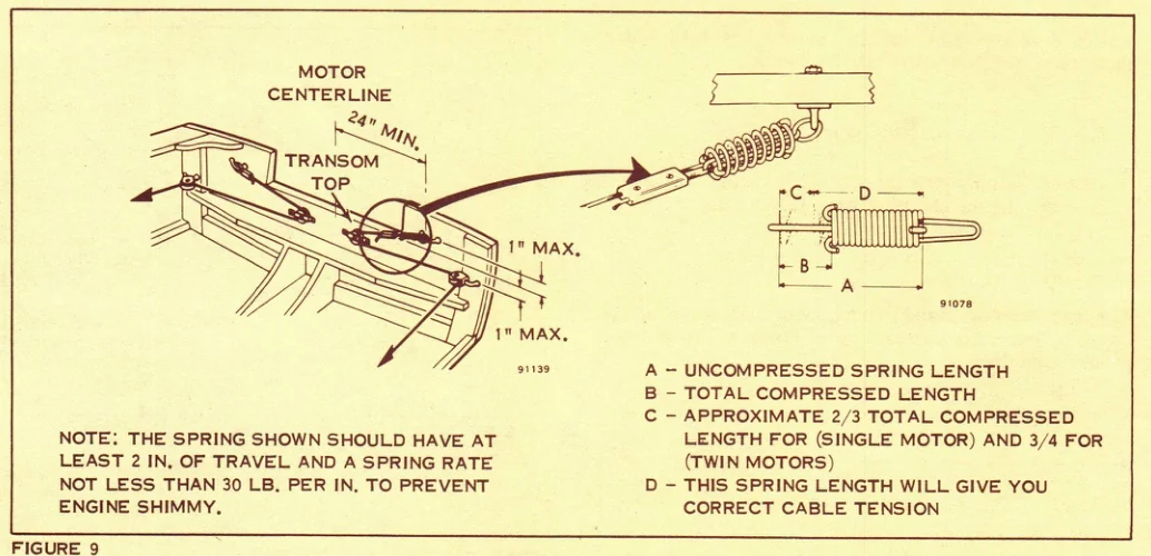
Steering system backlash can be caused by dimensional changes in your boat (because of moisture or dryness). To eliminate this backlash, install a spring in steering system where one cable end is attached to the transom. Use a 60 lb. spring, tightening the steering cable so that the spring is compressed approximately two-thirds of total compressed length. This will put a 40 lb. load on the spring.
On some boats, fishtailing may occur at higher speeds and a stronger spring may be needed. You can use a 100 lb. spring compressed approximately three-quarters of the total compressed length. This will give a 75 to 80 lb. load on the spring. See Figure 9.
▣ NOTE: Do not use the spring to compensate for improper pulley or cable anchor positioning.
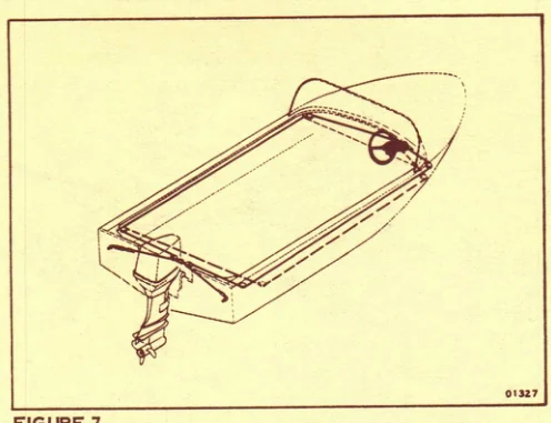
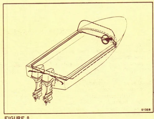
Attach cables as shown in Figure 7 for single engines or Figure 8 for dual engines.
IN ANY REMOTE STEERING SET-UP, OBSERVE THESE RULES:
- Use only stainless steel attaching hardware; never use brass. Do not substitute bolts, screws and hardware of unknown quality for parts furnished in kits.
- Always use locknuts, lockwashers and thru-bolts when fastening steering components to boat. Large diameter washers should be used on all soft load bearing surfaces such as wood, fiberglass and thin gauge aluminum. Never use wood or lag screws.
- Minimum fastener size on any boat steering attachments such as pulleys and steering anchors should be 1/4-28 (i.e. 1/4 inches in diameter and 28 threads per inch).
- Use only SAE fine series threads (i.e. 1/4-28, 5/16-24, 3/8-24 and 7/16-20, etc.) for attaching any steering hardware. Fine series threads give maximum strength per diameter of threaded fasteners.
OUTBOARD MARINE CORPORATION
Waukegan, Illinois
Historical reference: The bulletin specifically warns that a dual-engine installation must not use a single cable and tie bar. Steering system repairs and installations are safety-critical. Verify component compatibility and current marine safety requirements before use.