SB-1414 Rev. 1 - Hard Starting or Erratic Ignition
Issued June 1977, this Johnson Service Bulletin gives a step-by-step diagnostic procedure for 1969 and 1970 115 H.P. ignition systems, including pulse-pack voltage tests, coil and distributor checks, and 1972 ignition-system conversion instructions. The four original factory pages are reproduced below as searchable text with their technical photographs.

SB-#1414 Rev. 1
June, 1977

SUBJECT:  Hard Starting or Erratic Ignition

ON MODELS:  1969 and 1970 115 H.P.

    NOTE:  This procedure must be followed in a step by step sequence.

    NOTE:  After a malfunctioning part or connection is replaced or corrected,
           immediately recheck the last test that failed. (Before trouble
           shooting the ignition, make sure the battery is fully charged and
           in good condition.)

Step A. 1.  Check spark at plug end of high tension leads, using 3/8" gap on
            needle point spark tester.

        2.  If spark is good, check spark plugs.

    NOTE:  An engine miss could be due to excess spark plug voltage requirement.
           Champion L77J4 and AC M40FFX plugs are approved alternates with a
           lower voltage requirement. These plugs, gapped at .030, could fix
           an engine "miss" problem.

        3.  If the plugs are okay, check timing and points or sensor gap.
        4.  If above is okay, ignition is okay when cold. If ignition breaks
            down after warm-up trouble shoot immediately.
        5.  If spark is bad, go to Step B.

    NOTE:  On 1969 and 1970, 115 only, place a jumper wire between terminal
           7 and 9 on the terminal board and repeat Step A. If jumper provides
           correct spark, check ignition safety circuit assembly, rectifier,
           shift diodes and stator and replace defective part. Allow jumper
           to remain in place until all ignition system checks are completed
           and spark checks good. Then remove jumper and retest spark. If
           spark is not satisfactory when jumper is removed, see Step E2.
           NEVER ALLOW CUSTOMER TO OPERATE ENGINE WITH JUMPER IN PLACE.

Step B.     INPUT VOLTAGE

            Check wiring and battery for clean, tight and correct connections.
            Using a voltmeter, check input voltage at pulse pack at time of
            engine malfunction.
            Minimum voltages are as follows:

                     PRESTOLITE PULSE PACK

                  Cranking speed       9.5 volts
                  Idle speed          12.0 volts
                  High speed          12.5 volts
PAGE 2SERVICE BULLETIN #1414 Rev. 1
JOHNSON OUTBOARDS, DIVISION OF OUTBOARD MARINE CORPORATION, WAUKEGAN, ILLINOIS 60085
        2.  If voltage is okay, go to Step C.
        3.  If voltage does not meet minimum requirements, check battery, key
            switch, solenoids and other excessive power drains from battery
            including excessive starter motor current draw.

    NOTE:  Keep voltmeter connected so that pulse pack input voltage can be
           observed while testing further.

Step C.     PULSE PACK OUTPUT

        1.  Disconnect pulse pack blue output lead from coil primary lead.
        2.  Connect S-80 or M-80 neon tester blue lead to output lead coming
            from pulse pack and black tester lead to engine ground.
        3.  Set switch to position 1, depress load button A and crank engine.
        4.  If the neon lite is showing a strong regularly flashing or pulsing
            lite, go to Step D.
        5.  If lite is weak, erratic or intermittent, check sensor and connecting
            wires for grounds, opens, correct resistance and correct gap settings.
            If okay, replace pulse pack.
        6.  If no lite is showing, disconnect sensor from pulse pack and
            trigger manually (key switch on) as follows:

            PRESTOLITE PULSE PACK: Connect a test sensor and sensor rotor to
            sensor leads from pulse pack and spin test sensor rotor. Neon
            lite should flash at the same speed at which the test sensor rotor
            is being turned. If manual trigger does not produce the correct
            flash from the neon lite, the pulse pack is faulty and must be
            replaced.

Step D.     COIL TEST

        1.  Remove high tension coil lead from distributor cap. Reconnect
            coil primary leads (-) to ground and (+) pulse pack.
        2.  Connect coil high tension lead to a spark checker with gap set at
            ½ inch.
        3.  Crank engine.
        4.  If spark does not jump ½ inch gap, replace coil.
        5.  If spark consistently jumps ½" gap, coil is good. Go to Step E.

Step E.     DISTRIBUTOR CHECK

        1.  Check distributor cap, rotor and high tension spark plug leads per
            service manual. Caps, rotors or high tension leads are faulty or
            dirty if arcing occurs to or through any non-metallic surface while
            probing with high voltage. If all items and checks are good up to
            this point but engine misses, replace pulse pack.
        2.  Additional information on some specific problems is found in
            service bulletins 1237, 1239, 1273 and 1291. On 1969
            and 1970, 115 h.p. models, pay particular attention to service
            bulletin 1375 regarding the installation of a diode, part number
            383538, to eliminate hard starting.
PAGE 3SERVICE BULLETIN #1414 Rev. 1
JOHNSON OUTBOARDS, DIVISION OF OUTBOARD MARINE CORPORATION, WAUKEGAN, ILLINOIS 60085
Step F.     REPLACEMENT PULSE PACK 1969-1970 115 H.P.

        1.  If all the above procedures fail to eliminate a problem in the
            1969 and 1970, 115 h.p. engines equipped with a service replacement
            pulse pack, part number 385038, you can install a 1972 style
            ignition system as per Step G. This 1972 style ignition system
            can also be utilized when a replacement pulse pack, part number
            385038 is required.

Step G.     INSTALLING 1972 PULSE PACK ON 1969-1970 115 H.P.

        1.  To install a 1972 style ignition system on 1969 and 1970, 115
            h.p. engines in place of service replacement pulse pack, part
            number 385038, follow the procedure listed below:

            Install a part number 384522 phase II pulse pack with sensor
            rotor part number 316678.

            Remove the sensor leads from the base plate assembly and install
            part number 385200 lead assembly on the original base plate
            assembly or install a new base plate assembly, part number 384547.
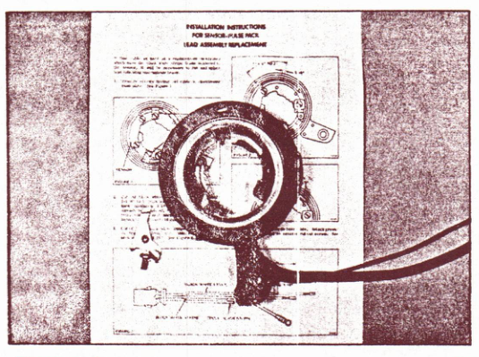
            Follow the instructions included with the assembly. Put the ground
            lead toward the clamp so that the sensor leads are within the
            channel for protection, as shown in Figure 1.

            Remove and discard the ignition safety circuit. Install a clipper
            circuit part number 588091. Refer to 1972, 125 h.p. engine service
            manual for installation instructions. Check engine timing with
            timing light. These modifications result in an engine with the
            ignition system similar to the 1972, 125 h.p. models.

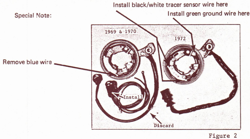
            Figure 2 shows the 1972 distributor base plate assembly on the
            right and the 1969 and 1970 distributor base plate on the left
            with lead assembly, part number 385200.


                         PHOTOS ON BACK OF PAGE.
PAGE 4SERVICE BULLETIN #1414 Rev. 1
JOHNSON OUTBOARDS, DIVISION OF OUTBOARD MARINE CORPORATION, WAUKEGAN, ILLINOIS 60085
JOHNSON OUTBOARDS
D. J. Leinonen
Technical Data Coordinator
D. J. Leinonen
Technical Data Coordinator
Related factory bulletins: SB-1375 - Ignition diode installation. The factory also references SB-1237, SB-1239, SB-1273, and SB-1291.